Time Domain-Based Moisture Measurements
Scott Anderson
Time Domain Reflectometry has been used for over 40 years in measuring the water content of various porous media including soils. The technology has proven itself to be accurate because of its consistent accuracy in reporting water content over large changes in soil Electrical Conductivity. Its use has been limited due to the high cost of traditional TDR equipment and its associated power consumption and bulk. As with other electromagnetic sensors it fails when the electrical conductivity of the measured medium becomes so high that it ‘shorts out’ the electromagnetic wave. This paper discusses the main advantages of Time Domain technology over competing technologies for measuring water content and outlines technological variations that extend its operating range to very high EC environments and to non-homogenous media.
Contents
Conventional Time Domain Reflectometry
Conventional TDR incorporates a TDR console connected to a waveguide through a coaxial cable. Inside the console are the 3 fundamental functions that form the necessary elements to acquire moisture readings. The first is a step function generator that develops a very fast rising voltage step. This step function propagates down the coax cable to the waveguide where it reflects from the end of the waveguide and returns through the cable back to the console. An ultra-high-speed digitizer gathers a digital picture of the returning waveform. Each point on the waveform is assigned to a time ordinate generated by a precision time base. Analysis of the waveform by software derives the propagation time of the wave during its travels along the waveguide rods. From first principles of wave propagation, the permittivity of the medium around the waveguide is,
ε = t2/4μl2
where l is the length of the waveguide, t is the round-trip propagation time of the step function traveling on the waveguide as measured by the TDR console, μ is the permeability of the medium and ε is the permittivity of the medium around the waveguide. This remarkable relationship is derived from the fact that the speed of light is governed by two universal constants associated with materials and free space – permeability and permittivity. Since permeability is constant for nearly all porous materials the equation above states that a precise measurement of propagation time will yield a precise measurement of permittivity. The permittivity derived is independent of all other variables including soil chemistry. Since the permittivity of water is more than an order of magnitude higher than the permittivity of other materials, the water content of almost any material mixed with water can be accurately derived from its measured permittivity.
A drawback of conventional TDR besides its cost and bulkiness is the coaxial cable. The cable has a limited bandwidth and acts as a low pass filter to the fast-rising wave propagating through it. This causes the rise time of the wave to be extended before it gets to the waveguide. The reflected wave thus has rounded features which spoil the resolution of the propagation time measurement. The elimination of the coax can yield sharp waveform features and improve the waveform feature-resolving capability of the TDR system.
The method developed by Acclima places the TDR console elements right on the end of the waveguide – thus eliminating the coax cable altogether.
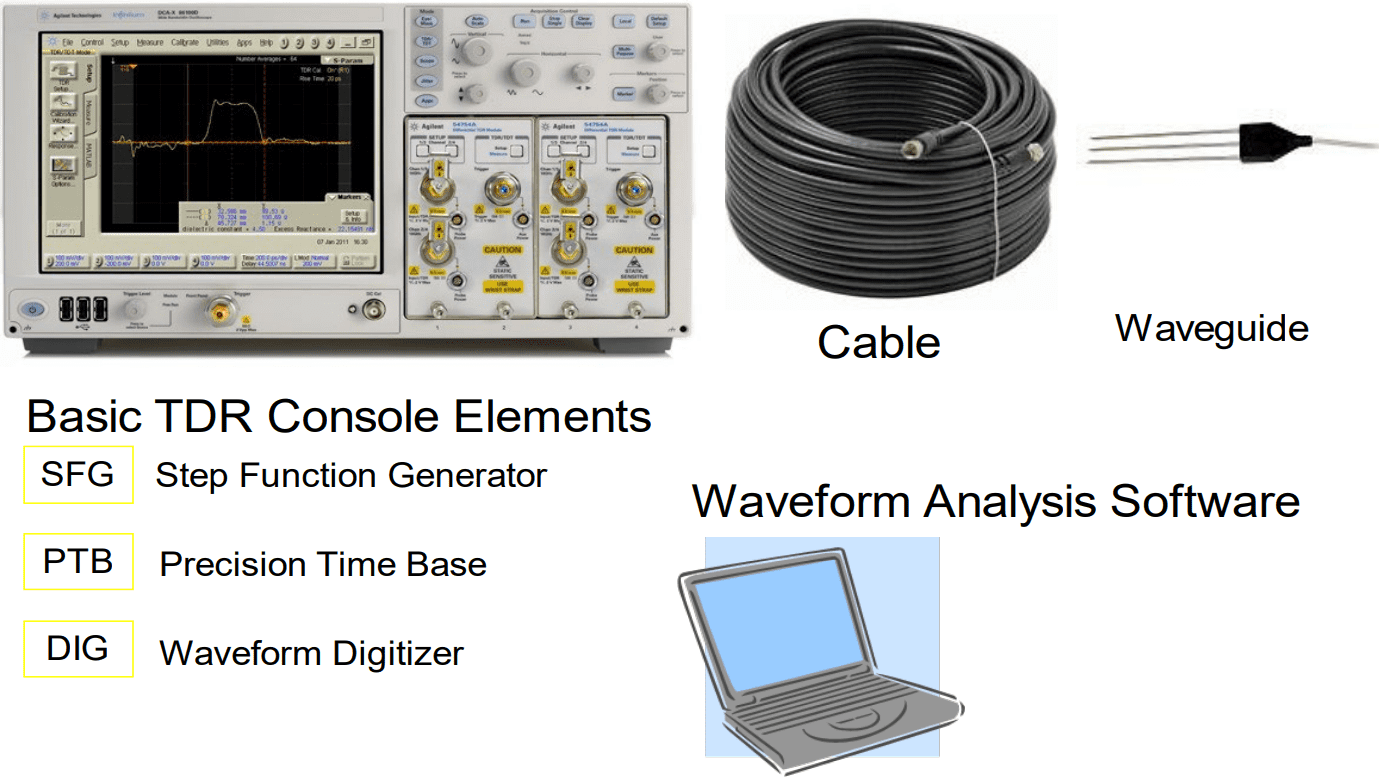
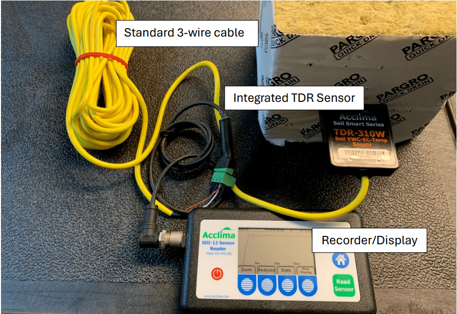
Figure 1. Typical TDR Setup above versus an Acclima TDR setup (option) below.
Integrated Time Domain Reflectometry
In the Integrated Time Domain Reflectometer shown in Figure 2, the basic elements of the TDR Console have been placed together with the waveguide in a common package. The Step Function Generator and Waveform Digitizer are both within a few millimeters of the center waveguide rod (the active element). The step function generator in the Acclima TDR315N produces a 1-volt step with 300 picosecond rise time applied directly to the waveguide and soil. The ultra-high-performance Digitizer and Precision Time Base record a 4095-point waveform over a 20 ns range with 5 picosecond resolution.
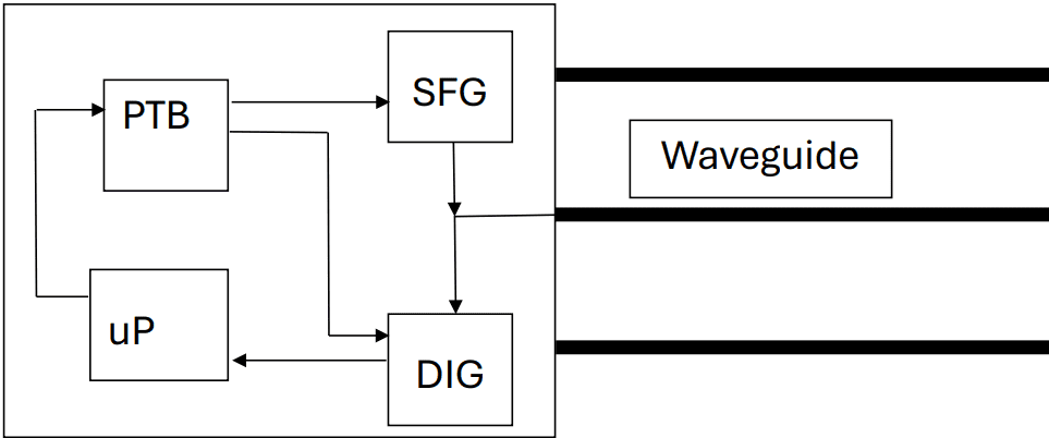
Figure 2. Integrated Time Domain Reflectometer.
The waveforms in Figure 3 were gathered in water with varying degrees of electrical conductivity. The incident waves appear on the far left. The reflected waves can be seen near the center of the figure for several different levels of salinity. As the salinity increases the waveform amplitudes decrease due to the attenuation of the propagated signal. But despite the amplitude decay the measured volumetric water contents are within 1% accuracy for all but the 5 dS/m sample which is within 1.6% accurate. This is one of the remarkable advantages of Time Domain-based sensors over other technologies. Beyond about 5dS/m the waveform becomes attenuated to the point that the rising edge of the reflected wave is undiscernible, and the sensor fails.
When saline water is present in soils, the mean free path of the ions is impeded, and the measured bulk conductivity is less than that of the saline water itself. Since it is the bulk conductivity that attenuates the waveform the integrated TDR sensor can obtain accurate readings in soils wetted with much higher EC values than the 5 dS/m limit depicted in
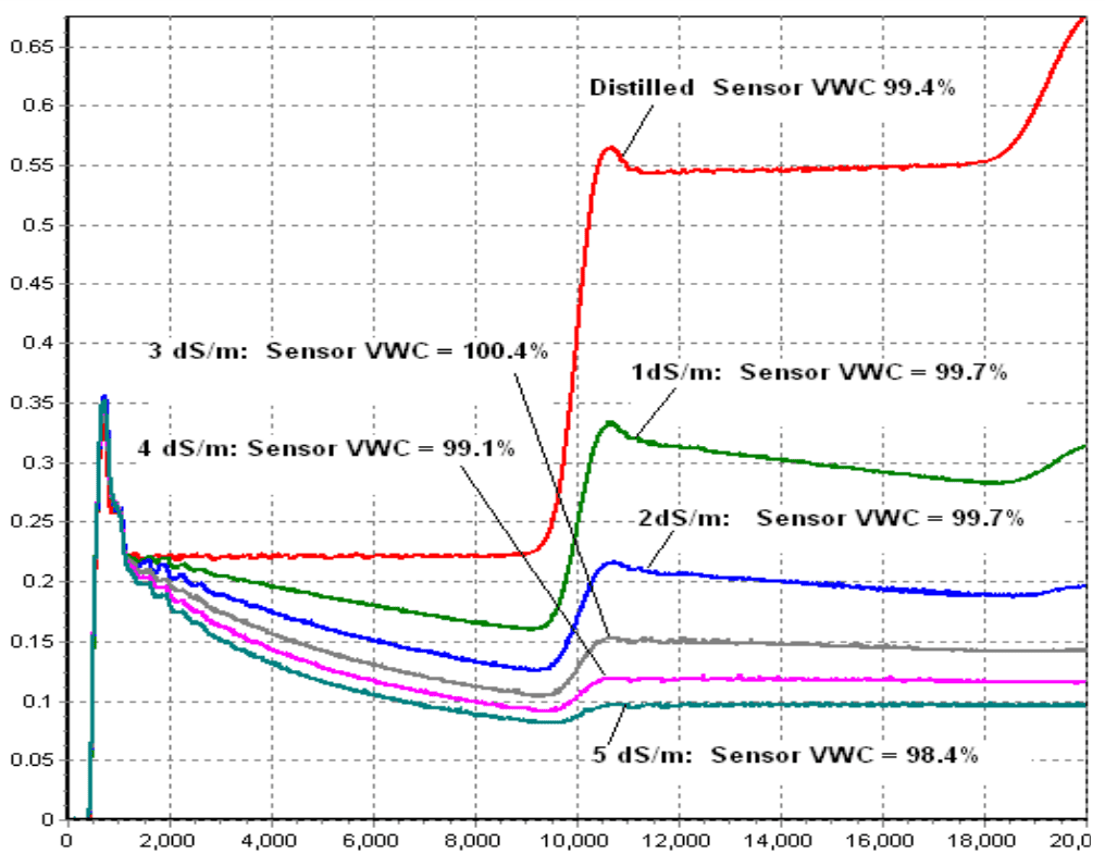
Figure 3. Waveforms and Measurement Accuracies of an Integrated TDR in water of various salinities, where the measurement is made in salt water with no other materials mixed in.
In each of the samples tested for the waveforms above, the VWC ‘truth’ was measured gravimetrically and is shown in the label next to each waveform. The sensor readings are also shown and are within 1% of the ‘truth’ values except for the 16 dS/m measurement which is 1.2% low. Figure 4 represents the environment where the TDR sensor is operating well in very high EC water but where the water is mixed with some other porous material causing the overall BULK EC to be lower than the water itself.
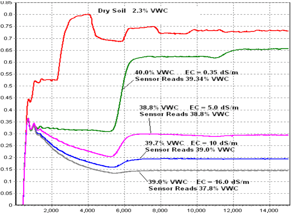
Figure 4. Waveforms and readings taken in clay-loam soil wetted to about 40% VWC with varying degrees of water electrical conductivity
Soil-Specific Calibration
Different soils pose different electrical field environments to electromagnetic sensors. This is due to particle specific surface area, variations in mineral permittivity, variations in particle shape etc. that vary from one soil to the next. These ‘electrical’ soil characteristics impact the EM field and cause most EM sensors to read different water content values for different soils of the same water content. Readings in clay soils, for example, may exhibit a 5% error relative to readings in mid-range soils of the same water content. The standard practice in the industry to get around these errors is to calibrate sensors for the specific soil in which they will be used. This is an additional burden to the user in deploying sensors.
As an electromagnetic wave passes through the soil it becomes distorted by these various electrical anomalies in the soil. Non-Time Domain sensors, which are unaware of these anomalies in deriving their reading, produce readings with significant differences from one
soil to the next.
In the Time Domain, the digitized waveform is a picture of the EM wave experience in passing through the soil. The ‘electrical’ features in the soil that cause the errors in the reading are presented in the waveform. Each different soil type has a unique waveform signature. That signature is modified by water content and salinity – but there are specific features in waveforms that are not masked by EC and VWC that reveal departures from theoretical waveforms and thus can be used to detect and quantify errors and even detect soil type.
This is a powerful advantage of Time Domain technology that has been exploited and developed by Acclima and is called ‘Soil Smart Technology’. Details in the information-rich waveform can be used to derive other information from the soil besides water content. The need for soil specific calibration disappears when this additional information in the TDR waveform is measured and utilized. Figures 5, 6, and 7 show TDR measurements in sand silt and clay using a sensor that was not specifically calibrated for the different soils.
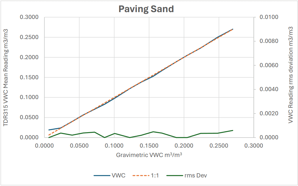
Figure 5. TRD-measured VWC in Pavers Sand.
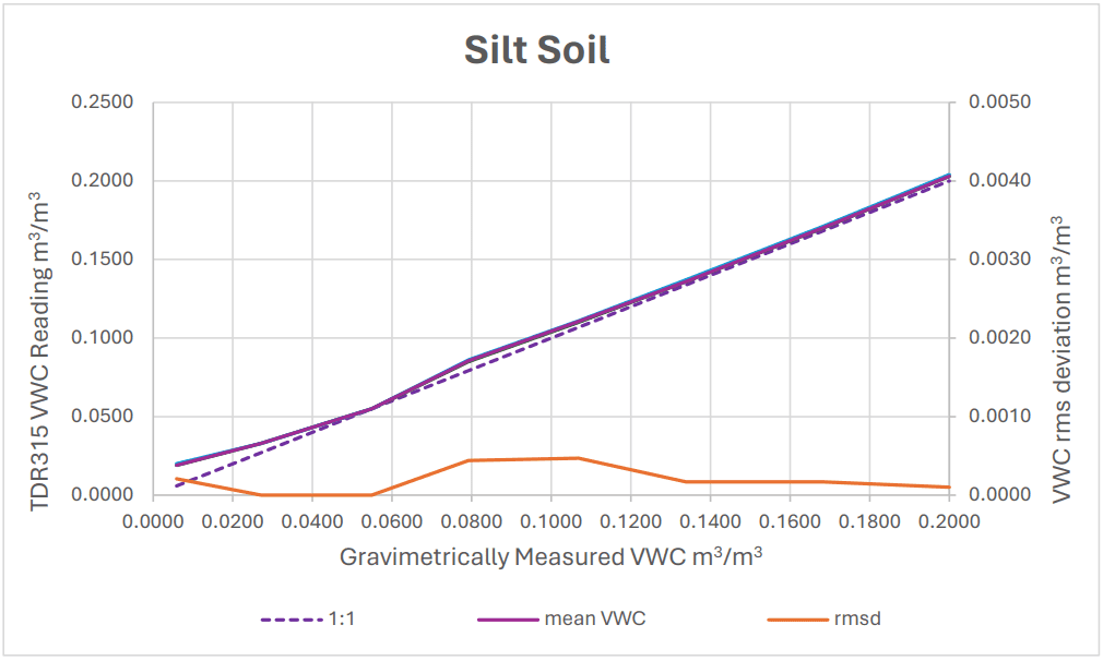
Figure 6. TDR measurements in silt soil.
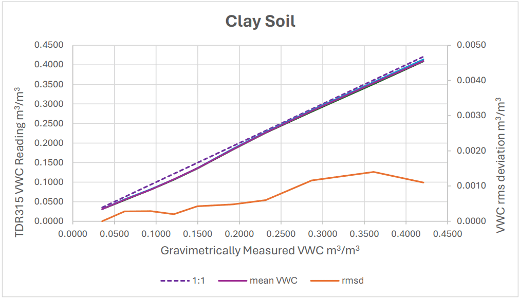
Figure 7. TDR measurements in Clay Soil.
Note: The measurement accuracy in these 3 different soils is typically 1% without soil
specific calibration.
Time Domain Transmissometry
TDR technology works very well in normal agricultural soils where the soil is homogenous, and the salinity is suitable for field crops. A basic feature of high resolution TDR is that it ‘sees’ the details of the medium composition along the waveguide including changes in water content. It provides high accuracy readings in homogenous media but has difficulty in ‘averaging’ the water content in media with severe, abrupt changes in water content. A popular medium for in-house plant growing is Rock Wool. This material is inhomogeneous and has air inclusions and high-density packing sites throughout its compressed structure. These severe density changes cause irregular waveforms. When the leading edge of the waveform encounters an air inclusion the higher impedance causes a positive reflection to be returned. When a densely filled water site is encountered a negative reflection is thrown back toward the source. The multiple reflections add vectorially to the main waveform and generate a picture of the impedance discontinuities along the path of the waveguide. This information overload can cause difficulties in finding the true overall propagation time. Sophisticated algorithms have been developed by Acclima to deal with these complex waveforms, but there is an easier, foolproof answer to reading average water content in nonhomogenous media.
We can avoid unwanted reflections by not measuring any reflections at all. Instead of applying the digitizer to the main active rod in the waveguide, it is attached to the distal end of the waveguide where it digitizes the incident wave instead of the reflected wave. This requires folding the waveguide back to the TDR body so that the Step Function Generator drives one end of the waveguide, and the Digitizer operates at the distal end of the foldedback conductor. This becomes a Time Domain Transmissometer, or TDT sensor.
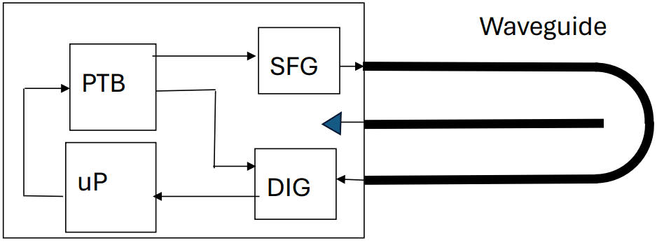
Figure 8. Time Domain Transmissometer - TDT
The TDT sensor has two major advantages over the TDR sensor and one drawback. Since it measures the propagated incident wave there are no losses in reflecting the wave from the end of the waveguide as in the TDR configuration. The signal-to-noise ratio of the propagated incident wave in high EC media is several times higher than a reflected wave in a TDR configuration. This means that the TDT sensor can operate accurately in much higher conductivity conditions than the TDR sensor.
The second major advantage is that the propagated wave averages the water content along the path of the waveguide. When a very wet spot is encountered the wave slows down. When an air inclusion is encountered the wave speeds up. By the time the incident wave returns to the digitizer, it has accumulated an average propagation time for all the discontinuous features along the waveguide. This average is then used in calculating water content. One might argue that reflections from these discontinuities will travel back to the source and then reflect forward again and eventually confuse the incident wave. That is certainly true, but those multiple reflections will arrive at the digitizer long after the original incident wave has been digitized. Thus, the effect of unwanted reflections can be ignored in a TDT system.
The disadvantage of TDT relative to TDR is that the waveguide does not have sharp points on the waveguide rods making the TDR sensor easy to insert into the medium. But in the TDT sensor the folded-back ‘knee’ can be made as a narrow point to lessen the insertion difficulty. A pilot ‘slot’ can also be cut into the medium creating a path into which the TDT sensor can be inserted. This insertion inconvenience is insignificant relative to the advantages of water content averaging and multiple reflection immunity that make the TDT sensor the ideal device for measuring water content at very high EC levels in Rock Wool and other inhomogeneous materials.
Time Domain Economics
Conventional time domain reflectometry equipment is very expensive to the point that its use is limited mainly to research applications. But the fundamental building blocks of TDR do not have to be expensive. Acclima developed Integrated TDR/TDT technology 24 years ago based on ultra-high-speed components used only in the few instances where they are needed and conventional silicon components elsewhere. After many years of experience this technology has been improved and cost reduced to the point that it is comparable in cost to lower performing vector voltmeter and capacitive sensors on the market today.
As a result of Acclima’s long experience with integrated TDR/TDT technology, the company has invested heavily in the development of an Application Specific Integrated Circuit (ASIC) which incorporates the step function generator, precision time base, waveform digitizer and communications circuitry on a single silicon chip measuring 2.5 mm square. This allows a full TDR or TDT sensor to be built using only 2 chips – a high-speed floating-point processor and the Acclima ASIC. This slashes cost, power consumption, and time in making measurements. It also allows TDR and TDT technology to be incorporated in tight spaces such as in the walls of access tubes for making water profile measurements and in smaller, low cost, highly accurate sensors for greenhouse and vertical farming use.


By Scott Anderson
© 2024 Acclima, Inc. All Rights Reserved